Autosar COM Module – Part 1
Introduction to COM Module
The COM (Communication) Module is a standardized software component in AUTOSAR Classic Platform that manages all signal-level communication between ECUs over the CAN bus network.
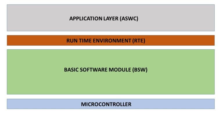
COM is a BSW (Basic Software) module located in the Services Layer that provides an abstraction between application software (which works with signals) and the communication bus system (which works with Protocol Data Units – PDUs).
The COM module is used to handle signal-based communication between the application software and the network. It converts application signals into network data and converts received network data back into signals.
COM Module Functionalities
The AUTOSAR COM (Communication) module is responsible for enabling signal-based communication between application software components and the in-vehicle network in a standardized and hardware-independent manner. It abstracts network details and ensures reliable, timed, and validated data exchange across ECUs.
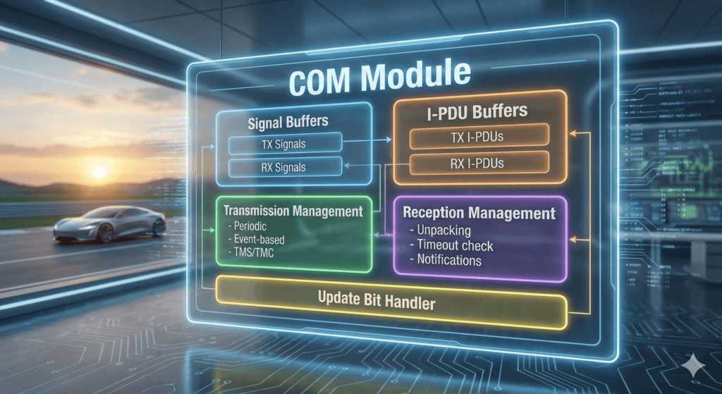
- Packing of AUTOSAR signals into I-PDUs for network transmission.
- Unpacking of received I-PDUs to extract individual signals.
- Providing received signal values to the RTE for application access.
- Handling of signal bit position, length, and placement within I-PDUs.
- Conversion of signal endianness to support different processor architectures.
- Handling of signed signals including sign extension and two’s complement representation.
- Assignment of configured initial values to signals during initialization.
- Support for periodic transmission of I-PDUs.
- Support for event-triggered transmission of I-PDUs.
- Enforcement of minimum delay time between consecutive transmissions of the same I-PDU.
- Control of start and stop behavior of I-PDU groups.
- Routing of signals from received I-PDUs into transmit I-PDUs for gateway communication.
- Monitoring of reception of signals and I-PDUs.
- Detection of signal and I-PDU timeouts.
- Execution of timeout actions such as setting default or invalid values.
- Generation of notification callbacks for reception, transmission, and timeout events.
- Management of update bits to indicate changes in signal values.
- Application of signal transfer and filtering properties as configured.
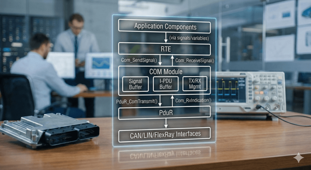
- Interaction with the RTE on the application side.
- Forwarding of I-PDUs to the PDU Router for delivery to lower communication layers.
COM Architecture Overview
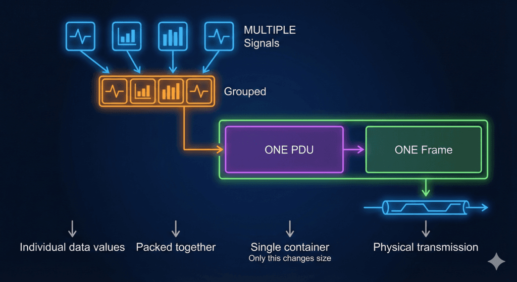
Signal, PDU, and Frame: Understanding Automotive Communication Hierarchy
Signal: The Atomic Unit of Information
Definition: A Signal is the smallest piece of data that can be transmitted in automotive networks. It represents a single piece of information, such as vehicle speed, engine temperature, or door lock status.
Key Characteristics:
- Atomic and indivisible unit of information
- Has defined data type (uint8, uint16, boolean, etc.)
- Contains specific bit position within a PDU
- Has defined scaling, offset, and byte order (Motorola/Intel)
- Can be transmitted individually or grouped with other signals
Example:
- Vehicle Speed = 65 km/h (represented as 650 in network value with 0.1 resolution)
- Engine RPM = 2150 rpm
- Turn Signal Status = LEFT/ RIGHT/ OFF
PDU (Protocol Data Unit): The Structured Data Container
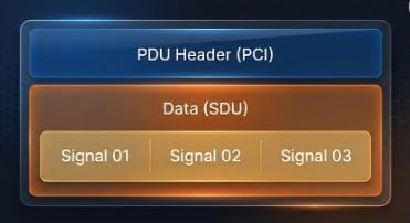
Definition: A PDU is a structured container that holds one or more signals (or signal groups) along with protocol control information. It serves as the standardized format for data exchange between different layers of the communication stack.
Components:
- SDU (Service Data Unit): The actual payload containing signal data
- PCI (Protocol Control Information): Layer-specific control information added/removed at each communication layer
PDU Types in AUTOSAR:
- I-PDU (Interaction Layer PDU): Used by COM module, contains application signals
- N-PDU (Network Layer PDU): Used for transport protocols
- L-PDU (Data Link Layer PDU): Used by CanIf/LinIf modules
Example PDU:
A “VehicleStatus” PDU might contain:
- Signal 01: Vehicle Speed (bits 0-15)
- Signal 02: Engine RPM (bits 16-31)
- Signal 03: Fuel Level (bits 32-39)
- Signal 04: Door Lock Status (bits 40-47)
CAN Frame Structure:
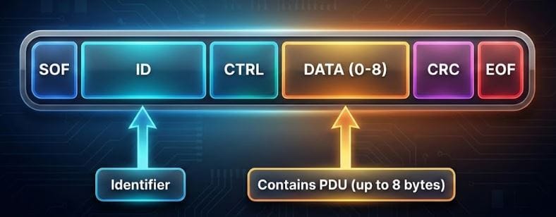
Relation between signal, pdu an frame: